(The) CCAT's MEOW


(The) CCAT's MEOW


(Mobile Energy Operations on Wheels)
Spring 2005 Phase -Yvonne & Scott
The CCAT's MEOW (formerly named the MRET) is a mobile renewable energy system designed to power local university and community events by showcasing solar-electric technology for interpretive purposes, in concordance with CCAT's mission statement. The project was conceived by Humboldt State University Appropriate Technology students in the Spring of 2003 and is nearing completion. The original proposal and schematics can be linked here: http://www.humboldt.edu/~ccat/mret/frames.html
Spring 2005 Phase Objectives:
1.) Design a new aluminum mounting rack for the top of the mobile trailer.
Considerations: The rack should be able to be easily raised and lowered for transportation and sturdy enough for the strongest north-coast wind storm or the meanest Arcata pot-hole. The rack should also be made to be versatile so any brand or size of panels can be installed to it.
2.) General electrical work on the interior of the trailer including:
A.) Installing a tri-metric meter to measure volts, amps and other important readings mainly involving the batteries
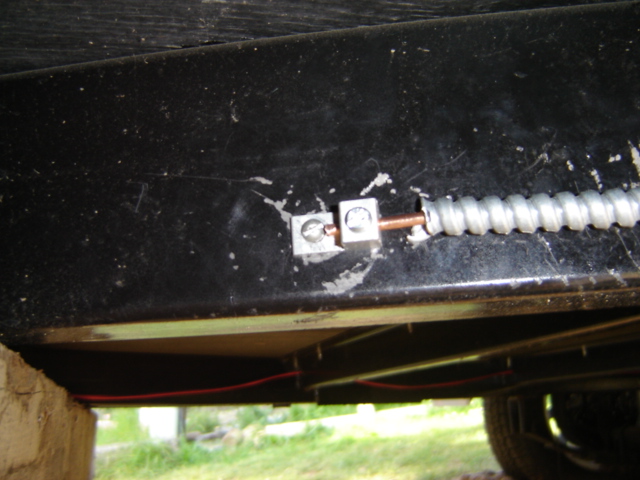
B.) Installing 2 AC outlets from the box and grounding the whole box to the frame
C.) Installing a spinning meter so AC electricity output can be measured
Designing The NEW Rack
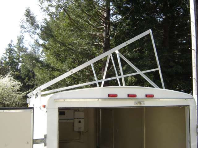
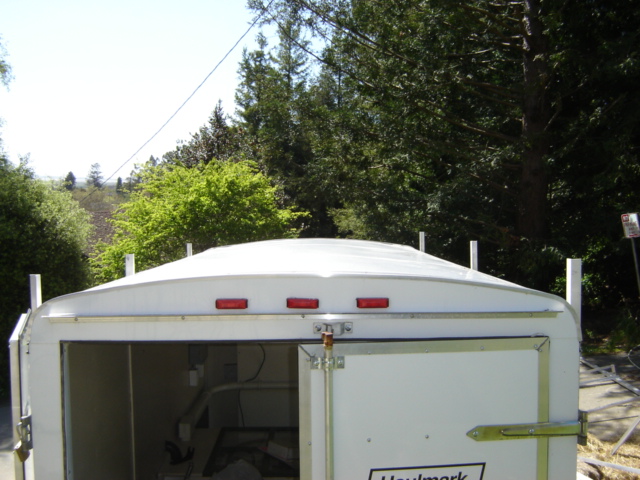
These are pictures of the old rack which was deemed unstable for travel and storage, and could not be adjusted for angle.
Our task was to design a newer, sturdier frame that could be easily raised up to a 30 degree angle and then lowered for storage/transportation. Since neither of us had barely any prior metal construction experience, we new this was not going to be a simple task.
We wanted the solar panels to sit above the roof since additional panels may be added to one side of the trailer in the future. However, the trailer has been plagued with leaks, so we decided not to mount the racks to the roof itself. Mounting to the roof, in a worst case scenario could create more leaks and in a best case scenario would create additional maintenance because someone would have to re-caulk the mounts occasionally to prevent leaks. We decided to attach aluminum supports to the side beams of the trailer and attach the rack to those supports.



![]() Removing
the interior wood panels was a painstaking process mainly due to the location of
battery box and other components in the way but was necessary to find what we
would be securing the outside supports to. It was determined that the
interior frame supports were not structurally strong enough to support the
intended weight, so we secured 2 new supports to the inside of the frame
on each side for a total of four. After this was completed and the
interior panels were replaced and the components re-secured to the wall, we were
able to attach (6) six-inch angled aluminum supports to which we
would attach the rack to.
Removing
the interior wood panels was a painstaking process mainly due to the location of
battery box and other components in the way but was necessary to find what we
would be securing the outside supports to. It was determined that the
interior frame supports were not structurally strong enough to support the
intended weight, so we secured 2 new supports to the inside of the frame
on each side for a total of four. After this was completed and the
interior panels were replaced and the components re-secured to the wall, we were
able to attach (6) six-inch angled aluminum supports to which we
would attach the rack to.
The next part of the design, was of course the rack design.
Before we could continue, we had to figure out what sort of raising/lowering mechanism that would support 300+ lbs and be easily accessed and operated.
Several ideas included:
Pros: Ease of design. Cons: Ease of use - it would require more than one person and they would have to be on ladders working simultaneously.
Pros: Ease of use. Cons: Mechanical difficulty with weight and design considerations. May be tough for one person to operate.
Pros: Ease of operation, weight considerations not a factor. Cons: Angle limited based on height and placement
Pros: Supreme ease of operation Cons: Mechanical design complexity, future maintenance and a drain on the batteries
After much consideration and several brainstorming sessions with engineering professors, solar-installers, students and others, we decided on the car jack system because of its ease of operation and simplified mechanics.


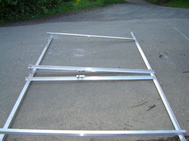
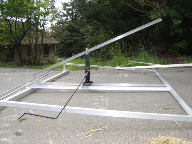
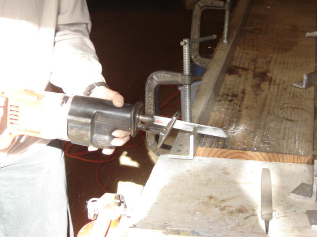
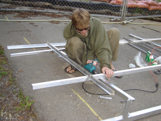
There were 3 main components of the rack: 1.) The upper frame to support and attach the panels 2.) The jack 3.) The lower frame which would support the jack and attach to the trailer via the 6 supports we secured to the trailer frame. We decided to construct the entire rack using the same angled aluminum that we used for the supports with an exception of one piece of square tubing that we salvaged from a local solar installer. The aluminum was 1 1/2" x 1 1/2" and was 3/8 inches thick. One of the more challenging design issues was securing all the angled pieces to each other. In order to do this we need to drill many holes, and all bolts and nuts used needed to be weatherized with an anti-seizing agent. We also needed to make many difficult precise cuts of our own to get our desired lengths and sizes of pieces we wished to use. Safety goggles, gloves, and multiple securing clamps are definitely recommended for anyone attempting to cut lots of aluminum at home. More than one (minor) injury was incurred in this phase and demonstrates our true dedication to appropriate technology!

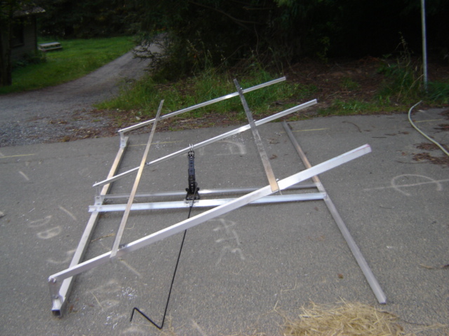
As we neared completion of the frame, we test-raised the frame and were excited to see it in action. We were also excited to reach our desired angle of 30 degrees. We were however, concerned with the slight wobble and tilt that was exhibited by the frame and thought that once the panels were attached, the weight would be distributed and the problem corrected.
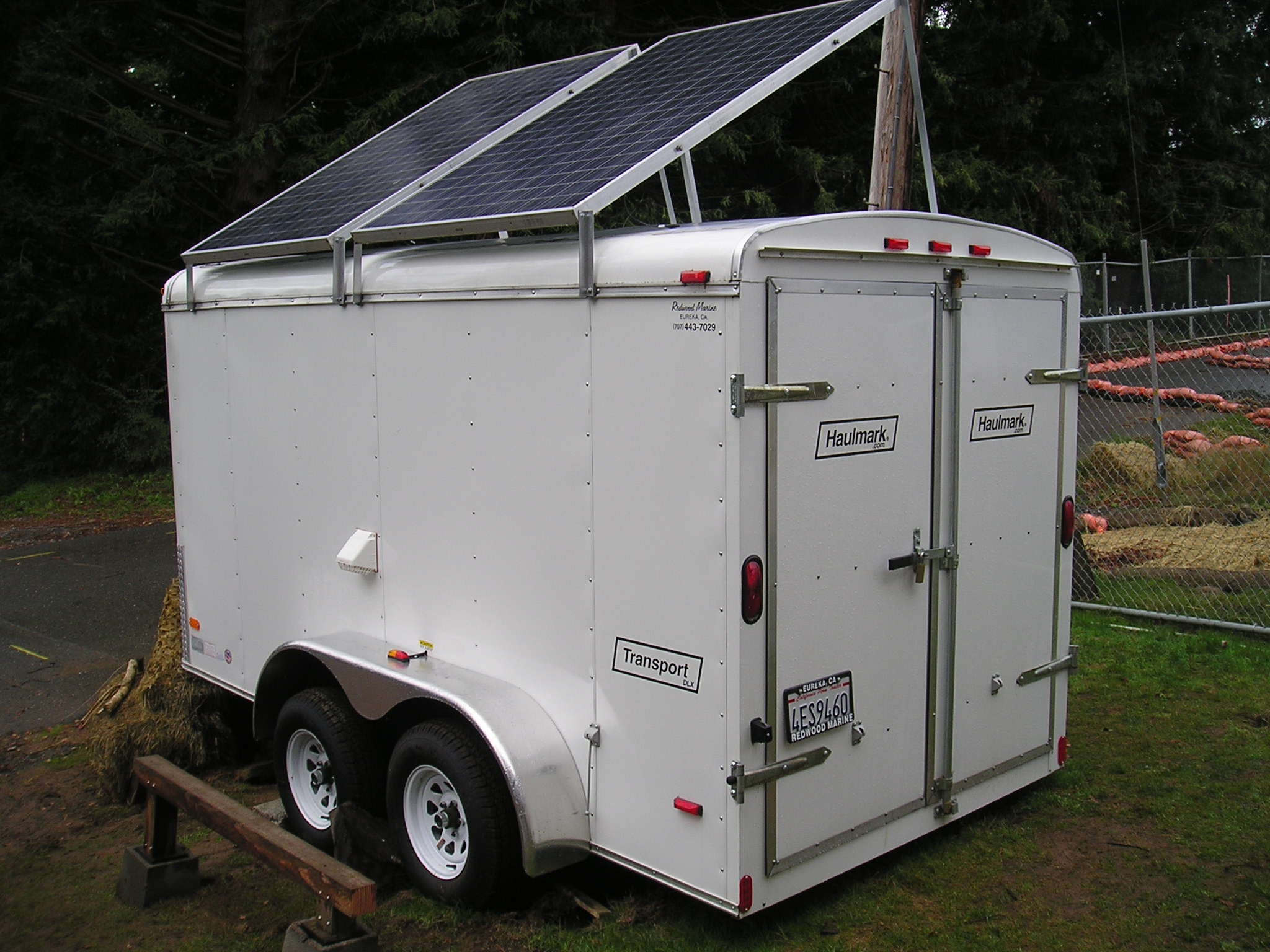
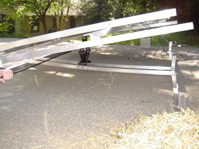
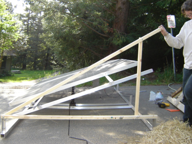
After attaching the panels, the frame was ready to be raised for the final test before we attached the frame to the roof. As we began to raise the jack, it became painfully obvious that the lengthwise wobble had not gone away. To further complicate the matter, the aluminum was bowing under the weight in several places and we were now only to achieve a 20 degree angle.



![]()
 Unfortunately the aluminum was bowing in several places

 We
were both obviously frustrated after all our hard work that the frame was not
sturdy enough to support the panels. At the present time, we plan to
reinforce the center cross beam that rests on the jack with a 1 1/2" square
tube. We are also going to add a 2" x 3" square tube connecting the three
cross-beams. Hopefully this should stop the bowing and the panels can be secured
to the trailer in the coming weeks.
 Electrical
Work

The second part of the project composed of electrical work mainly on the interior of the trailer.
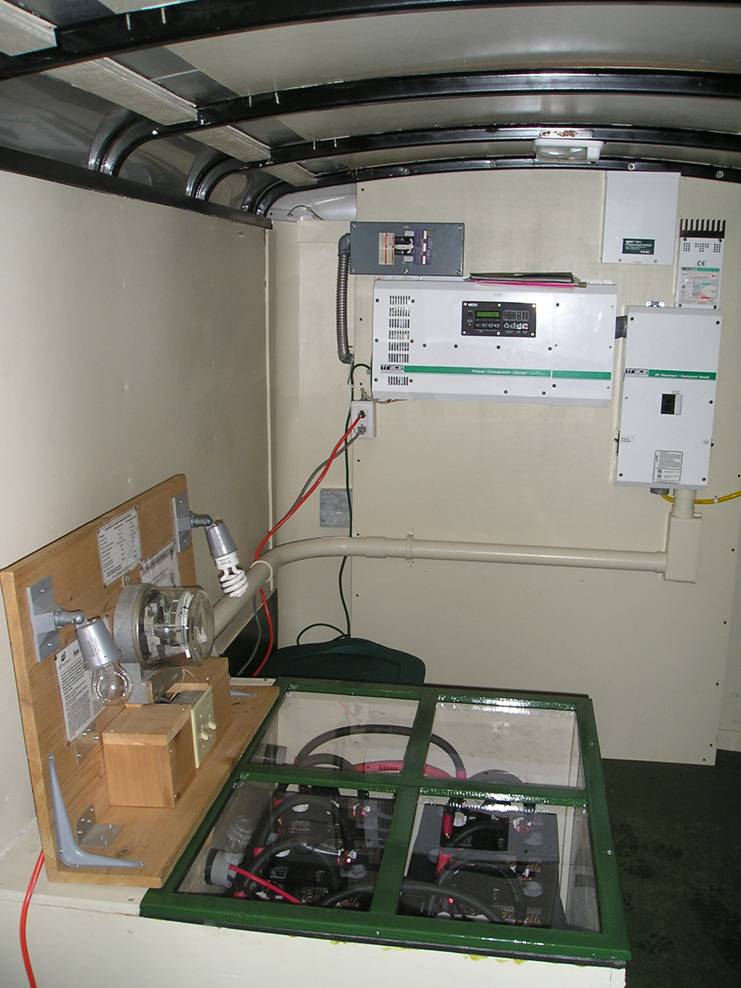
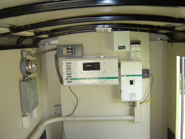
These are before and after pictures of the interior of the trailer. The picture on the left shows the interior of the trailer at the end of last semester, set up to power an interpretive display demonstrating energy consumption of incandescent vs. compact fluorescent light bulbs.


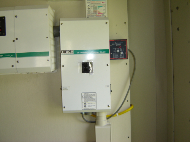
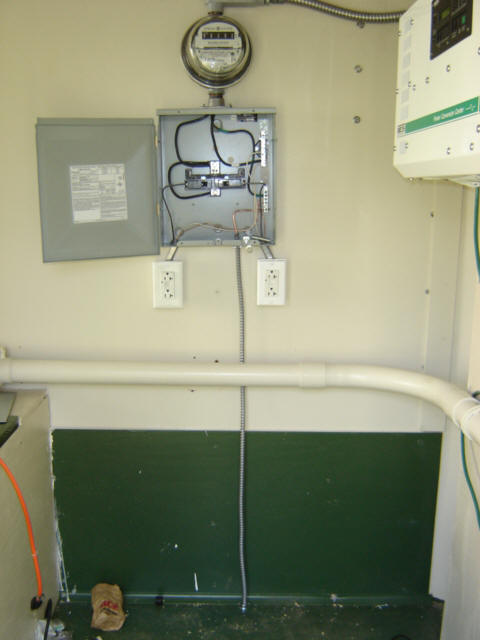
4.) Installed meter and got it spinning.
5.) Installed 2 AC plug outlets.
6.) Installed AC grounding wire and attached it to the frame.


![]()

Many thanks to the following people:
Ben Scurfield, Scurfield Solar, Arcata, CA
Lonny Grafman, Appropriate Tech. Instructor, Humboldt State University
Glenn and all the rest of the folks at CCAT as well as all those who stopped by and offered their opinions, suggestions and helping hands. See ya over the summer!
Useful Associated Links
MRET CCAT Homepage with original project proposal ~ http://www.humboldt.edu/~ccat/mret/frames.html
HSU Campus Center for Appropriate Technology ~ http://www.humboldt.edu/~ccat/
Home Power Magazine ~ http://www.homepower.com/
Redwood Alliance ~ http://www.redwoodalliance.org/