 |
 |
 |
|||||||||||||||||||||||||||||||||
|
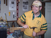
Construction
|
|||||||||||||||||||||||||||||||||||
|
The Bike: |
|||||||||||||||||||||||||||||||||||
 |
 |
||||||||||||||||||||||||||||||||||
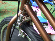
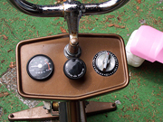
| Figure 1: Tension adjustment "brakes" | Figure 2: Tension adjustment kob | ||||||||||||||||||||||||||||||||||
 |
|||||||||||||||||||||||||||||||||||
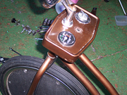
| Figure 3: Tension adjustment "brakes" and knob removed. | |||||||||||||||||||||||||||||||||||
 |
|||||||||||||||||||||||||||||||||||
 |
|||||||||||||||||||||||||||||||||||
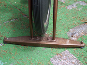
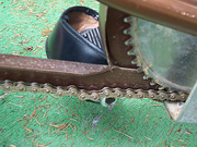
| Figure 4: Rusted links wouldn't flex | Figure 5: Original front stand | ||||||||||||||||||||||||||||||||||
|
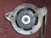
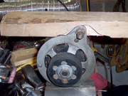
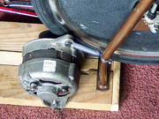
The Alternator: After attaching the wheel to the alternator (fig. 9), I figured it would be too long and would put too much pressure on the shaft bearings. I had to think of another way to attach the wheel without permanently modifying the alternator. It's proper owner (the FJ40) will need it back. |
|||||||||||||||||||||||||||||||||||
 |
 |
||||||||||||||||||||||||||||||||||
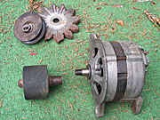
| Figure 6: Removed pulley and fan from alternator in preparation of attaching the rubber wheel. | Figure 7: I grinded the rusted nut off the bolt on the rubber wheel so I could attach it to the alternator. | ||||||||||||||||||||||||||||||||||
 |
|||||||||||||||||||||||||||||||||||
 |
|||||||||||||||||||||||||||||||||||
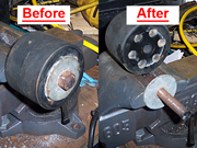
| Figure 8: The rusted nut on the wheel (left) and after is was removed (right). | |||||||||||||||||||||||||||||||||||
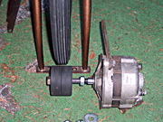
| Figure 9: Rubber wheel attached to extended shaft, but it was too long. | |||||||||||||||||||||||||||||||||||
| When I removed the rusted nut and bolt from the rubber wheel, I discovered that it was holding two thinner wheels together. Coincidentally, the width of the thinner wheels very close to the length of the shaft.
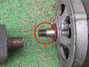
But the hole in the center of the rubber wheel was not quite large enough to fit onto the shaft. The outer half of the shaft had a diameter of 1/2", but the inner half was 5/8" (fig. 10), so that portion of the rubber wheel would need to be enlarged. |
|||||||||||||||||||||||||||||||||||
 |
|||||||||||||||||||||||||||||||||||
| Figure 10: The inner portion of the shaft is wider than the outer. Part of the wheel will need to be drilled. | |||||||||||||||||||||||||||||||||||
|
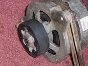
The new hole needs to be exactly centered and perpendicular through the wheel, otherwise the hole wouldn’t be centered and the wheel would wobble. Since that's very difficult to accomplish with a hand-held drill, I used a drill press and an 11/16” hole saw bit (Sorry, no photos of the process). Then, because the wheel was just wide enough to fit onto the shaft with no room for the washer and nut, I needed to countersink them by using a 1 1/4” hole saw bit and drilling down 1/8”, just enough to get the nut started, then it would compress the rubber wheel when it tightened down (fig. 11-12). |
|||||||||||||||||||||||||||||||||||
 |
|||||||||||||||||||||||||||||||||||
 |
|||||||||||||||||||||||||||||||||||
| Figure 12: Front view of the washer and nut securing the wheel onto the alternator. | |||||||||||||||||||||||||||||||||||
| Figure 11: The outside of the wheel had to be enlarged to fit the washer and nut. | |||||||||||||||||||||||||||||||||||
|
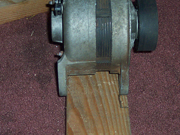
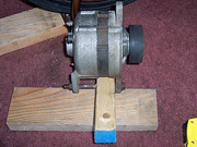
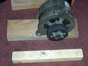
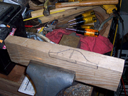
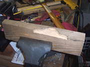
The Base: I first drilled a hole in a 2x2 and attached it to the alternator (fig. 14), then sketched an outline of the path the alternator would travel as it moved back and forth for adjustment (fig. 15). This could give me an outline of where I would need to carve the 2x4. Then I transferred that sketch to the 2x4 and chiseled it out (figs. 16-19). |
|||||||||||||||||||||||||||||||||||
 |
 |
||||||||||||||||||||||||||||||||||
| Figure 14: I used a 2x2 to get the correct position for the hole and to sketch what will be trimmed. | |||||||||||||||||||||||||||||||||||
| Figure 13: The 2x4 is too wide for the alternator. I will trim 3/8" off of a secton 2x4's side. | |||||||||||||||||||||||||||||||||||
 |
 |
||||||||||||||||||||||||||||||||||
| Figure 15: I sketched the area that will be trimmed onto a 2x2 first. | Figure 16: I then transferred the sketch from the 2x2 onto the 2x4. | ||||||||||||||||||||||||||||||||||
 |
|||||||||||||||||||||||||||||||||||
 |
|||||||||||||||||||||||||||||||||||
| Figure 17: Chiseling away... | |||||||||||||||||||||||||||||||||||
| Figure 18: A job well chiseled. | |||||||||||||||||||||||||||||||||||
 |
|||||||||||||||||||||||||||||||||||
| Figure 19: The finished product ... and it fits. | |||||||||||||||||||||||||||||||||||
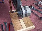
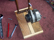
| I then attached another 2x4 to make up the other side of the base and used two small pieces of 2x2 as spacers to allow the alternator to move freely. I screwed a length of 1x2 to each end of the base for added strength (fig. 20). I attached the base to the bike using the holes where the original base was attached (fig. 21). | |||||||||||||||||||||||||||||||||||
 |
|||||||||||||||||||||||||||||||||||
 |
|||||||||||||||||||||||||||||||||||
| Figure 21: The base connected to the bike, with the wheel snug against tire. | |||||||||||||||||||||||||||||||||||
| Figure 20: The finished base, just before being attached to front of bike. | |||||||||||||||||||||||||||||||||||
|
Tension Spring: |
|||||||||||||||||||||||||||||||||||
 |
|||||||||||||||||||||||||||||||||||
| Figure 22: The tension spring attached to alternator and front fork. | |||||||||||||||||||||||||||||||||||